


Telecommunications Towers can cause nearby AM broadcast station transmitting antenna signals to weaken in coverage. The FCC is aware of this effect and has created AM Compliance Rules & Regulations Part 1-30002-30005. Owners of Telecom Towers are required to follow these Rules & Regulations when constructing or modifying their towers.
Fortunately, there are ways to correct this effect and allow the AM signal to travel in the directions it was designed for. The process of identifying the effects of Telecommunications Towers on local AM broadcast station signals and correcting this effect is known as AM Compliance or “AM Detuning.”
FCC Required Actions to Protect AM Broadcast Stations
-
-
Determine the proximity of the Telecommunications Tower to local AM stations.
-
Determine the electrical height of the Telecommunications Tower at local AM stations frequency.
-
Determine if Telecommunications Tower requires attention per FCC Part 1-30003 Rules & Regs.
-
Notify the affected AM stations, inform them of their right to comment, within 30 days of notice.
-
Install detuning equipment, if necessary, on the Telecommunications structure.
-
Adjust detuning network to minimize effect upon AM station.
-
Measure AM radio stations signal to verify compliance requirements are met.
-
Detuning Equipment Configuration
The most common detuning equipment arrangement consists of 3 or 4 wires that run vertically and parallel to the telecom tower being detuned. These wires are attached mechanically and electrically to the tower at a height of approximately 100 feet, or just below the lowest telecom antenna array. The wires are spaced approximately 24 inches from the tower face through the use of electrical insulator arms. At a level of approximately 8 ft above ground the wires are joined together with a wire hoop which is insulated from the tower. A single wire is used to join this hoop to the Detuning Network.
The Detuning Network consists of a series capacitor and in some cases a coil. One end of this network is connected to the wire coming from the detuning wire hoop, the other end of the network goes to ground.
Detuning Network
The Detuning Network typically consists of a vacuum variable capacitor and an adjustable inductor coil. These components are connected in series and provide a means of presenting a negative or positive reactance at the radio station frequency. Together with the Detuning Skirt they are tuned to minimize the re-radiation from the skirted tower structure at the radio station frequency of interest.
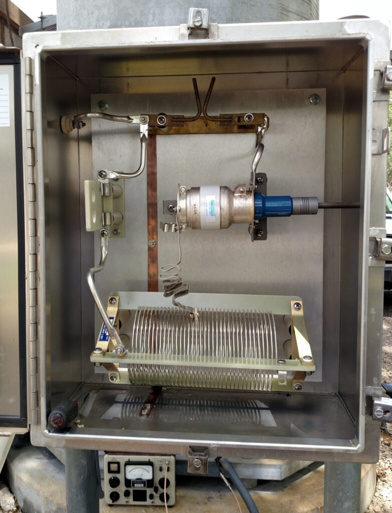
Typical Detuning Network